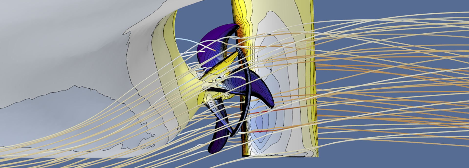

They say a picture is worth a thousand words – and here are 13 examples that prove it’s true. Take a peek behind the scenes at these amazing pictures that show the magic of computational fluid dynamics (CFD). What do these fascinating images reveal, and how can they help you to save money and fuel, among other benefits?
Are you ready to experience 13 glimpses into a world of fascinating underwater insights? Every year CFD calculations increase in accuracy and complexity, boosted by increases in computing power and extensive R&D efforts. These calculations help experts to find and solve problems quickly, and to fine-tune hardware to make it as efficient as possible. Read on to see what’s going on beneath the surface – without the need to put on a wetsuit.
1. See things you’ve never seen
Take a deep dive and swim around your propeller to see the wake and flow with your own eyes.

This is something that you can only do virtually. You’ll be surprised how good it looks – and how much it can reveal about the interactions between your vessel’s propeller and rudder, especially if you have a CFD expert on hand to interpret for you.
2. Find problems early – and stop them happening
Before it was possible to create amazing CFD pictures like the one below, unwanted issues like a propeller hull vortex came to light too late, when a vessel was already in operation.

This kind of cavitating vortex appears at low speeds when there isn’t enough space around the propeller, and it leads to an unpleasant high-pitched noise and severe vibration. Fixing the problem when the vessel is operational isn’t easy and requires strips of metal to be added to the hull to adjust the flow. Thanks to Wärtsilä’s OPTI Design process, this problem can be spotted early and addressed in the design phase.
3. Optimise cavitation in the design phase
Some cavitation is necessary to ensure an optimal propulsion system, but too much cavitation creates erosion and noise. How can you find the sweet spot?
CFD is the answer. The white in the picture below is cavitation and the patch by the propeller blade shows a problem in the next picture – bubbles of cavitation that will collapse and possible erosion on the blades and nozzle.


Making adjustments is much easier (and less costly) if you spot the problem in the design phase. Identifying the issue before your vessel hits the water will reduce maintenance costs and downtime.
Hand-picked related content:
Six things about computational fluid dynamics that might surprise you.
4. Reduce cavitation in an existing vessel
What if cavitation hasn’t been optimised? Maybe you’ve noticed that your propeller needs more maintenance than you expected, or it is generating significant vibration or noise. Or perhaps new regulations mean you need to make efficiency improvements.
It may not be feasible to make changes to the shaft or hull structures of an existing vessel, but there are big improvements that can be made to your propeller design.
The white areas in the top picture show excessive cavitation which was eroding the propeller blades.

The bottom picture shows the new propeller which, thanks to CFD, doesn’t suffer from erosive cavitation, even at low vessel speeds. As you can see, the blades are now clear of unwanted cavitation.
5. Improve manoeuvrability
Thruster flow plays a very important role in vessel manoeuvrability when entering and exiting ports. These pictures show a typical flow situation before and after optimisation.
In the next picture, the sharp corners on the edge of the tunnel cause the water to slow down – seen as a blue area on the lower left after the thruster tunnel. When water slows down in this way it disrupts the inflow for the propeller.

In the next picture, rounding the corners and losing the sharp angles improves the propeller inflow and increases thruster performance. The lower load fluctuations also mean that the propeller will have a longer lifetime.

These enchanting, almost other-worldly pictures show the importance of designing an integrated system – every hull is a different shape and length; taking every aspect of the vessel into account is the only way to fully optimise thruster performance.
Hand-picked related content:
Thruster optimisation is particularly important in one maritime segment. Here’s how short sea shipping operators can increase efficiency and optimise performance.
6. Evaluate performance in real operational conditions
This picture shows a virtual vessel hull and how it responds to waves.

To maximise efficiency and performance gains, it’s important to evaluate a vessel in its actual operating conditions, including wave patterns and drift angles. Some Wärtsilä customers no longer use model tests because OPTI Design gives such accurate results.
7. Know what to expect during sea trials – and beyond
Did you know that OPTI Design can even help to accurately predict what speeds you can expect to see during sea trials and beyond? The next graph shows ballast power-speed predictions and how closely they map to actual trial results.

As sea trials are usually performed in ballast conditions and not in loaded conditions, they don’t give an accurate picture of how fast a vessel will be able to sail in the real world, when loaded with cargo or passengers. OPTI Design can give an accurate speed prediction for loaded conditions – and the result is more accurate than predictions from model tests.
8. Improve waterjet performance
Many parts of a vessel can be optimised using simulations, making the vessel perform better as a whole. Take waterjets: the top picture shows a self-propulsion simulation that helps with mapping the velocity upstream of the inlet ducts. Doing this enables experts to optimise the shape of the ducts, improving overall performance.

The picture below shows the entire propulsion system in operation and how it interacts. This particular study was conducted to improve the complex interaction effects between the swirly jet and the steering device.

9. Help achieve EEXI and CII compliance
For existing vessels, OPTI Design can show exactly which energy-saving devices and improvements will work best together to achieve compliance with EEXI and CII regulations.
These pictures show how the Wärtsilä EnergoFlow improves the water flow towards the propeller. This increases efficiency and reduces the amount of power needed to move the vessel through the water.
The picture below is the situation without EnergoFlow – note the red, turbulent area.

Now look at the next picture. See how much smaller the red area has become! This is the situation after EnergoFlow has been added.

10. Explore different visualisation options
OPTI Design gives lots of different visualisation options – the next picture shows how the flow is directed, entering the EnergoFlow and going to the propeller.

To achieve the best performance between the EnergoFlow and propeller, it is very important to position the device correctly in the water flow. This kind of picture helps experts to optimise the performance.
11. Improve the ship’s efficiency at slower speeds
These pictures show the flow lines behind the Wärtsilä EnergoProFin, a clever energy-saving device installed behind the propeller. It reduces vortexes, thereby decreasing drag. This can cut fuel consumption by 2–5%.


OPTI Design makes it possible to model the effects of energy saving devices on your vessel. This helps estimate the potential savings and shows which combination will offer the best results.
One potential benefit of this approach is that it can improve propulsion efficiency at lower speeds, improving the ship’s CII rating.
Hand-picked related content:
Learn how you can achieve a good CII rating and be competitive at the same time – download the white paper: How to ensure a good CII rating while staying competitive.
12. Redesign your vessel for a new operational profile
If your requirements change or regulations mean your vessel can no longer operate at the same speed, OPTI Design can help optimise the ship for its new profile.
For example, a container vessel may have been designed to operate at 25 knots, but now needs to reduce its speed to comply with regulations. CFD calculations can be used to optimise the propeller for the new, lower speed.
In this case the original propeller is shown in blue. The optimised slow-steaming design is shown in orange. It has fewer blades, a lower blade area ratio, a bigger diameter and a new blade shape.

The new design optimises cavitation and efficiency. The grey data points in the graph below show the benefits – a clear increase in performance with the new design, with power savings of around 5%.

13. See how solutions impact your vessel
These next two pictures show the dramatic difference that even a relatively small device can make to propulsion performance. The first picture is without the EnergoProFin installed – note the strong vortex by the rudder.

The picture below shows how much the device has reduced the vortex, cutting losses and significantly improving fuel consumption.

CFD gives you the power to optimise propulsion and minimise costs
So there you have it – 13 captivating images that show the power of CFD and how it can be used to model how different changes will interact.
One of the most effective ways to harness the power of CFD is with Wärtsilä’s OPTI Design methodology. This methodology evaluates the propeller design together with the vessel, allowing accurate predictions and improvements to be made.
OPTI Design is based on 25 years of experience in the field, extensive R&D efforts and continuous research and development. It is the result of highly experienced design engineers having access to the very latest and most sophisticated software and analysis tools. Today it enables our experts to help you to make your ships more efficient with data-driven decision making that saves fuel and reduces emissions. It also enables other improvements that directly benefit passengers, crew and the maritime environment.
Propulsion optimisation could make your ship as much as 15% more efficient. Interested? Here’s the easy way to get started with Wärtsilä OPTI Design.


